Resistor & Types of Resistors | Fixed, Variable, Linear & Non-Linear:
Types of Resistors Linear/Nonlinear
Uses / Application of Resistors
Resistor units
Decoding resistor surface-mount markings
Series resistors
Parallel resistors
What is a resistor?
Ans: The resistor is a passive electrical component to create resistance in the flow of electric current.. What is Resistor coding? Ans: The Resistor Color Code Calculator decodes and identifies a value and tolerance of 4 band wire wound resistors
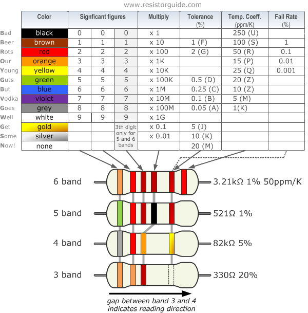
Resistor color code chart
The chart below shows how to determine the resistance and tolerance for resistors. The table can also be used to specify the color of the bands when the values are known. An automatic resistor calculator can be used to quickly find the resistor values.
Types of resistors using color codes/ Color bands:
4 band resistor
The four band color code is the most common variation. These resistors have two bands for the resistance value, one multiplier and one tolerance band. In the example on the left these bands are green, blue, red and gold. By using the color code chart, one finds that green stands for 5 and blue for 6. The value is thus 56·100 =5600 Ω. The golden band means that the resistor has a tolerance of 5%. The resistance value lies therefore between 5320 and 5880 Ω.
If the tolerance band would be left blank, the result is a 3 band resistor. This means that the resistance value remains the same, but the tolerance is 20%.
5 band resistor
Resistors with high precision have an extra band to indicate a third significant digit. Therefore, the first three bands indicate the significant digits, the fourth band is the multiply factor and the fifth band represents the tolerance. There are exceptions to this. For example, sometimes the extra band indicates failure rate (military specification) or temperature coefficient (older or specialized resistors). Please read the section “Color code exceptions” for more information.
Shown example: brown (1), yellow (4), purple (7), black (x1), green (0.5%): 147 Ω 0.5%.
6 band resistor
Resistors with 6 bands are usually for high precision resistors that have an additional band to specify the temperature coefficient (ppm/K). The most common color for the sixth band is brown (100 ppm/K). This means that for a temperature change of 10 ˚C, the resistance value can change 0.1%. For special applications where temperature coefficient is critical other colors
Shown example: orange (3), red (2), brown (1), green (x10), brown (1%), red(50 ppm/K): 3.21 k Ω 1% 50 ppm/K.
Resistor & Types of Resistors | Fixed, Variable, Linear & Non-Linear:
Types of Resistors Linear/Nonlinear
Resistors are available in different size, Shapes and materials. We will discuss all possible resistor types one by one in detail with pro and cons and application/uses.
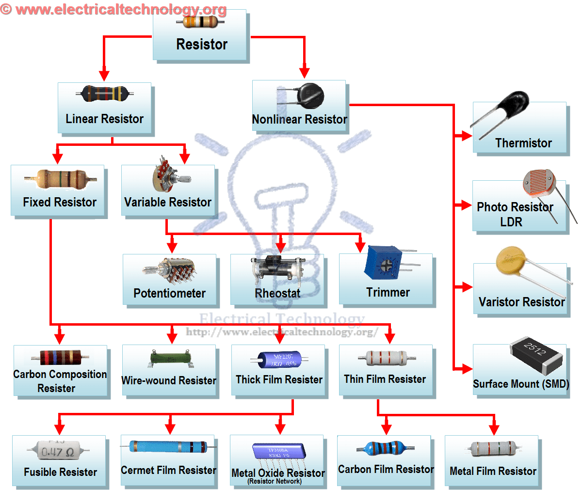
Different Types of Resistor Chart/Tree.
There are two basic types of resistors.
Linear Resistors
Non Linear Resistors
1. Linear Resistors:
Those resistors, which values change with the applied voltage and temperature, are called linear resistors. In other words, a resistor, which current value is directly proportional to the applied voltage is known as linear resistors.
Generally, there are two types of resistors which have linear properties.
1. 1. Fixed Resistors 1. 2. Variable Resistors
1. 1. Fixed Resistors
As the name tells everything, fixed resistor is a resistor which has a specific value and we can’t change the value of fixed resistors.
Types of Fixed resistors.
Carbon Composition Resistors
Wire Wound Resistors
Thin Film Resistors
Thick Film Resistors
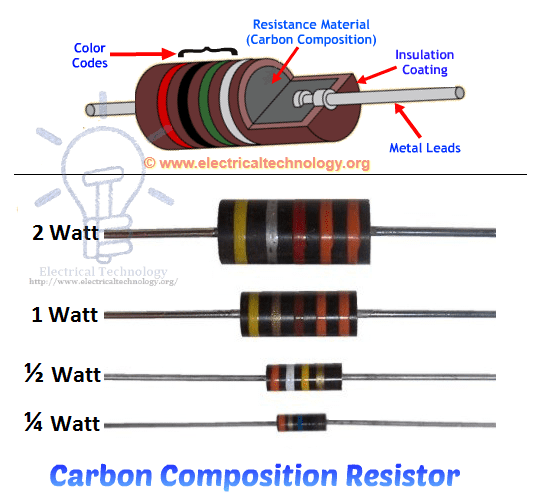
1. 1. 1) Carbon Composition Resistors
A typical fixed resistor is made from the mixture of granulated or powdered carbon or graphite, insulation filler, or a resin binder. The ratio of the insulation material determines the actual resistance of the resistor. The insulating powder (binder) made in the shape of rods and there are two metal caps on the both ends of the rod.
There are two conductor wires on the both ends of the resistor for easy connectivity in the circuit via soldering. A plastic coat covers the rods with different color codes (printed) which denote the resistance value. They are available in 1 ohm to 25 mega ohms and in power rating from ¼ watt to up to 5 Watts.
Carbon Composition Resistors.Construction and Wattage Rating
Characteristic of Fixed Resistors
Generally, they are very cheap and small in size, hence, occupy less space. They are reliable and available in different ohmic and power ratings. Also, fixed resistor can be easily connected to the circuit and withstand for more voltage.
In other hand, they are less stable means their temperature coefficient is very high. Also, they make a slight noise as compared to other types of resistors.
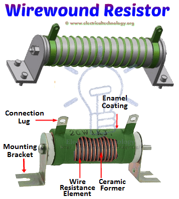
1. 1. 2) Wire wound Resistors
Wire wound resistor is made from the insulating core or rod by wrapping around a resistive wire. The resistance wire is generally Tungsten, manganin, Nichrome or nickel or nickel chromium alloy and the insulating core is made of porcelain, Bakelite, press bond paper or ceramic clay material.
The manganin wire wound resistors are very costly and used with the sensitive test equipments e.g. Wheatstone bridge, etc. They are available in the range of 2 watts up to 100 watt power rating or more. The ohmic value of these types of resistors is 1 ohm up to 200k ohms or more and can be operated safely up to 350°C.
in addition, the power rating of a high power wire wound resistor is 500 Watts and the available resistance value of these resistors are is 0.1 ohm – 100k Ohms.
Construction of Wire wound Resistors
Advantages and Disadvantage of Wire wound Resistors
Wire wound resistors make lower noise than carbon composition resistors. Their performance is well in overload conditions. They are reliable and flexible and can be used with DC and Audio frequency range. Disadvantage of wire wound resistor is that they are costly and can’t be used in high frequency equipments.
Application/Uses of Wire Wound Resistors
Wire wound resistors used where high sensitivity, accurate measurement and balanced current control is required, e.g. as a shunt with ampere meter. Moreover, Wire wound resistors are generally used in high power rating devices and equipments, Testing and measuring devices, industries, and control equipments.
1. 1. 3) Thin Film Resistors
Basically, all thin film resistors are made of from high grid ceramic rod and a resistive material. A very thin conducting material layer overlaid on insulating rod, plate or tube which is made from high quality ceramic material or glass. There are two further types of thin film resistors.
1. Carbon Film Resistors 2. Metal Film Resistors
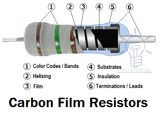
1. 1. 3. 1) Carbon Film Resistors
Carbon Film resistors contains on an insulating material rod or core made of high grade ceramic material which is called the substrate. A very thin resistive carbon layer or film overlaid around the rod. These kinds of resistors are widely used in electronic circuits because of negligible noise and wide operating range and the stability as compared to solid carbon resistors.
Construction of Carbon Film Resistors & Its labels.
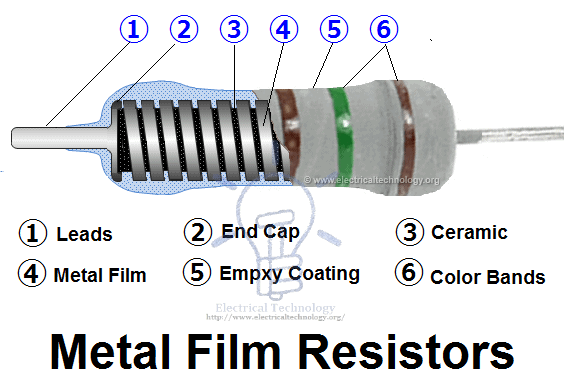
1. 1. 3. 2) Metal Film Resistors
Metal film resistors are same in construction like Carbon film resistors, but the main difference is that there is metal (or a mixture of the metal oxides, Nickel Chromium or mixture of metals and glass which is called metal glaze which is used as resistive film) instead of carbon. Metal film resistors are very tiny, cheap and reliable in operation. Their temperature coefficient is very low (±2 ppm/°C) and used where stability and low noise level is important.
Metal Film Resistor. Construction and name of internal parts.
1.1.4) Thick Film Resistors
The production method of Thick film resistors is same like thin film resistors, but the difference is that there is a thick film instead of a thin film or layer of resistive material around. That’s why it is called Thick film resistors. There are two additional types of thick film resistors.
1. Metal Oxide Resistors 2. Cermet Film Resistors 3. Fusible Resistors
1.1.4.1) Metal Oxide Resistors
By oxidizing a thick film of Tin Chloride on a heated glass rod (substrate) is the simple method to make a Metal oxide Resistor. These resistors are available in a wide range of resistance with high temperature stability. In addition, the level of operating noise is very low and can be used at high voltages.
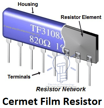
1.1.4.2) Cermet Oxide Resistors
In the cermet oxide resistors, the internal area contains on ceramic insulation materials. And then a carbon or metal alloy film or layer wrapped around the resistor and then fix it in a ceramic metal (which is known as Cermet). They are made in the square or rectangular shape and leads and pins are under the resistors for easy installation in printed circuit boards. They provide a stable operation in high temperature because their values do not change with change in temperature.
Cermet Film Resistor Network Construction
1.1.4.3) Fusible Resistors
These kinds of resistors are same like a wire wound resistor. When a circuit power rating increased than the specified value, then this resistor is fused, i.e. it breaks or open the circuit. That’s why it is called Fusible resistors. Fusible restores perform double jobs means they limit the current as well as it can be used as a fuse.
They used widely in TV Sets, Amplifiers, and other expensive electronic circuits. Generally, the ohmic value of fusible resistors is less than 10 Ohms.
1. 2) Variable Resistors
As the name indicates, those resistors which values can be changed through a dial, knob, and screw or manually by a proper method. In these types of resistors, there is a sliding arm, which is connected to the shaft and the value of resistance can be changed by rotating the arm. They are used in the radio receiver for volume control and tone control resistance.
Following are the further types of Variable Resistors
1. Potentiometers 2. Rheostats 3. Trimmers
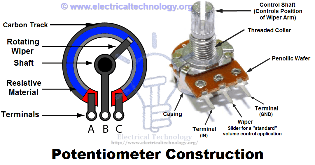
1.2.1) Potentiometers
Potentiometer is a three terminal device which is used for controlling the level of voltage in the circuit. The resistance between two external terminals is constant while the third terminal is connected with moving contact (Wiper) which is variable. The value of resistance can be changed by rotating the wiper which is connected to the control shaft.
Potentiometer Construction
This way, Potentiometers can be used as a voltage divider and these resistors are called variable composition resistors. They are available up to 10 Mega Ohms.
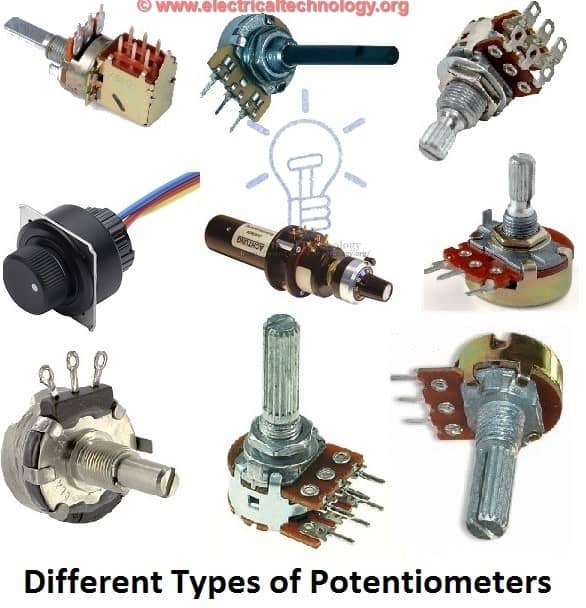
Different Types of Potentiometers
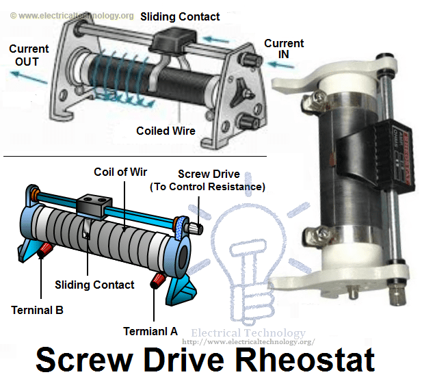
1.2.2) Rheostats
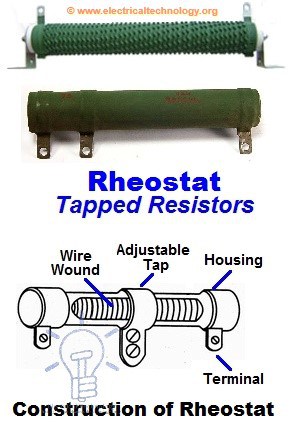
Rheostats are a two or three terminal device which is used for the current limiting purpose by hand or manual operation. Rheostats are also known as tapped resistors or variable wire wound resistors.
Types of Rheostats resistor and construction of Screw Drive Rheostat
To make a rheostats, they wire wind the Nichrome resistance around a ceramic core and then assembled in a protective shell. A metal band is wrapped around the resistor element and it can be used as a Potentiometer or Rheostats (See the below note for difference between Rheostat and Potentiometer).
Construction of Tapped Rheostat
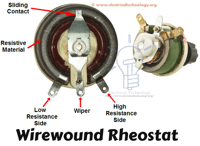
Variable wire wound resistors are available in the range of 1 ohm up to 150 Ohms. The available power rating of these resistors is 3 to 200 Watts. While the most used Rheostats according to power rating is between 5 to 50 Watts.
Wirewound Rheostat Construction
Good to Know:
What is the main Difference between Potentiometer and Rheostats?
Basically, there is no difference between Potentiometer and Rheostat. Both are variable resistors. The main difference is the use and circuit operation, i.e. for which purpose we use that variable resistor?
For example, if we connect a circuit between resistor element terminals (where one terminal is a general end of the resistor element while the other one is sliding contact or wiper) as a variable resistor for controlling the circuit current, then it is Rheostats.
In the other hand, if we do the same as mentioned above for controlling the level of voltage, then this variable resistor would be called a potentiometer. That’s it.
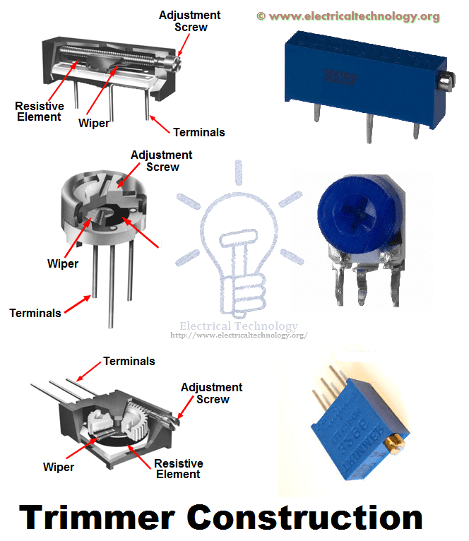
1.2.3) Trimmers
There is an additional screw with Potentiometer or variable resistors for better efficiency and operation and they are known as Trimmers. The value of resistance can be changed by changing the position of screw to rotate by a small screwdriver.
Construction of Different Types of Trimmers. Trimmer potentiometer Resistor construction
They are made from carbon composition, carbon film, cermet and wire materials and available in the range of 50 Ohms up to 5 mega ohms. The power rating of Trimmers potentiometers are from 1/3 to ¾ Watts.
2. Non Linear Resistors
We know that, nonlinear resistors are those resistors, where the current flowing through it does not change according to Ohm’s Law but, changes with change in temperature or applied voltage.
In addition, if the flowing current through a resistor changes with change in body temperature, then these kinds of resistors are called Thermisters. If the flowing current through a resistor change with the applied voltages, then it is called a Varistors or VDR (Voltage Dependent Resistors).
Following are the additional types of Non Linear Resistors.
1. Thermisters 2. Varisters (VDR) 3. Photo Resistor or Photo Conductive Cell or LDR
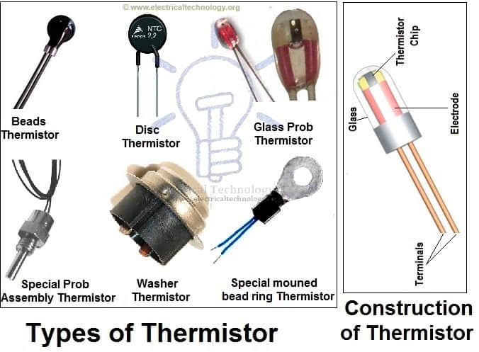
2.1) Thermisters
Thermisters is a two terminal device which is very sensitive to temperature. In other words, Thermisters is a type of variable resistor which notices the change in temperature. Thermisters are made from the cobalt, Nickel, Strontium and the metal oxides of Manganese. The Resistance of a Thermister is inversely proportional to the temperature, i.e. resistance increases when temperature decrease and vice versa.
Types of Thermisters & Its Construction
It means, Thermisteres has a negative temperature coefficient (NTC) but there is also a PTC (Positive Temperature Coefficient) which a made from pid barium titanate semiconductor materials and their resistance increases when increases in temperature.
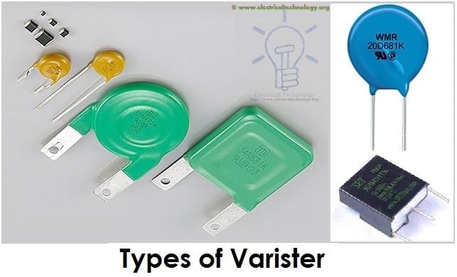
2.2) Varisters (VDR)
Varisters are voltage dependent Resistors (VDR) which is used to eliminate the high voltage transients. In other words, a special type of variable resistors used to protect circuits from destructive voltage spikes is called varisters.
When voltage increases (due to lighting or line faults) across a connected sensitive device or system, then it reduces the level of voltage to a secure level i.e. it changes the level of voltages.
Types of Varisters
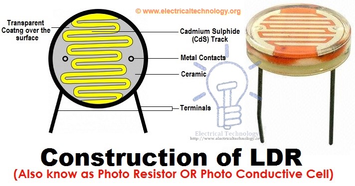
2.3) Photo Resistor or Photo Conductive Cell or LDR (Light Dependent Resistors)
Photo Resistor or LDR (Light Dependent Resistors) is a resistor which terminal value of resistance changes with light intensity. In other words, those resistors, which resistance values changes with the falling light on their surface is called Photo Resistor or Photo Conductive Cell or LDR (Light Dependent Resistor). The material which is used to make these kinds of resistors is called photo conductors, e.g. cadmium sulfide, lead sulfide etc.
Construction of LDR (Light Dependent Resistor), Photo-resistor or photo conductive cell
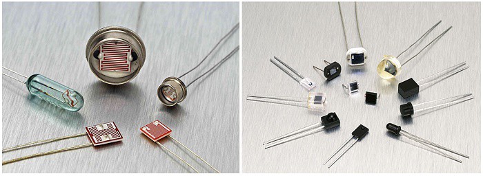
When light falls on the photoconductive cells (LDR or Photo resistor), then there is an increase in the free carriers (electron hole pairs) due to light energy, which reduce the resistance of semiconductor material (i.e. the quantity of light energy is inversely proportional to the semiconductor material). It means photo resistors have a negative temperature coefficient.
Application and Uses of Photo Resistors/Photo Conductive Cells or LDR
These types of resistors are used in burglar alarm, Door Openers, Flame detectors, Smock detectors, light meters, light activated relay control circuits, industrial, and commercial automatic street light control and photographic devices and equipments.
Uses / Application of Resistors
Practically, both types of resistors (Fixed and Variable) are generally used for the following purposes.
Resistors are used:
I. For Current control and limiting
II. To change electrical energy in the form of heat energy
III. As a shunt in Ampere meters
IV. As a multiplier in a Voltmeter
V. To control temperature
VI. To control voltage or Drop
VII. For protection purposes, e.g. Fusible Resistors
VIII. In laboratories
IX. In home electrical appliances like heater, iron, immersion rod etc.
X. Widely used in the electronics industries
Resistor units
The electrical resistance of a resistor is measured in ohms. The symbol for an ohm is the greek capital-omega: Ω. The (somewhat roundabout) definition of 1Ω is the resistance between two points where 1 volt (1V) of applied potential energy will push 1 ampere (1A) of current.
As SI units go, larger or smaller values of ohms can be matched with a prefix like kilo-, mega-, or giga-, to make large values easier to read. It’s very common to see resistors in the kilohm (kΩ) and megaohm (MΩ) range (much less common to see miliohm (mΩ) resistors). For example, a 4,700Ω resistor is equivalent to a 4.7kΩ resistor, and a 5,600,000Ω resistor can be written as 5,600kΩ or (more commonly as) 5.6MΩ.
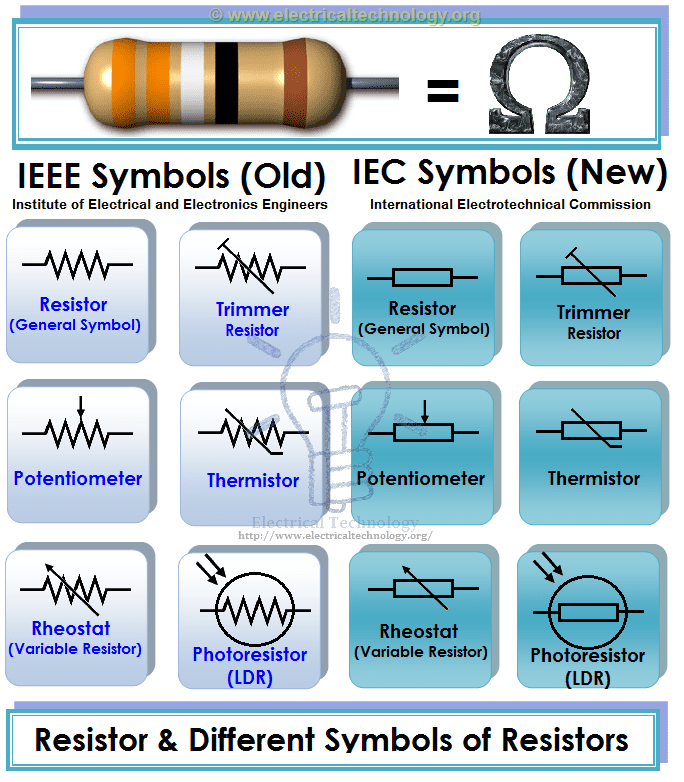
Schematic symbol
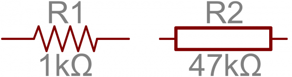
All resistors have two terminals, one connection on each end of the resistor. When modeled on a schematic, a resistor will show up as one of these two symbols:
Two common resistor schematic symbols. R1 is an American-style 1kΩ resistor, and R2 is an international-style 47kΩ resistor.
Decoding resistor surface-mount markings
SMD resistors, like those in 0603 or 0805 packages, have their own way of displaying their value. There are a few common marking methods you’ll see on these resistors. They’ll usually have three to four characters – numbers or letters – printed on top of the case.
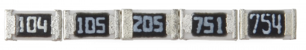
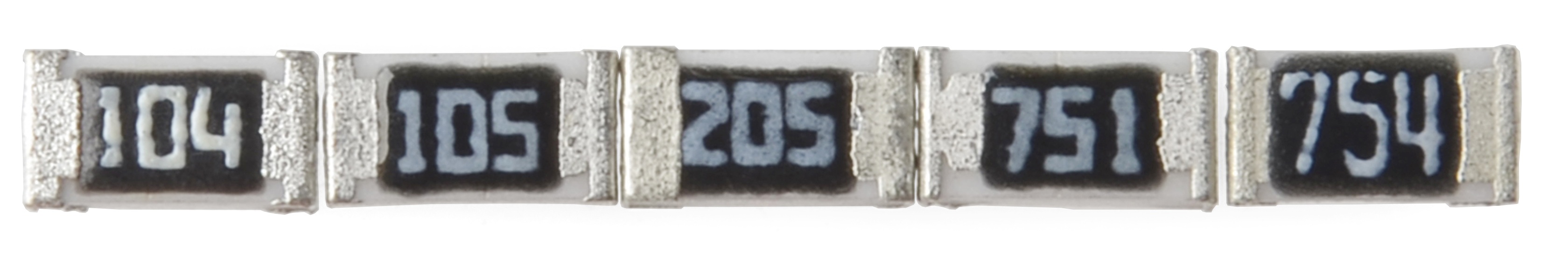
If the three characters you’re seeing are all numbers, you’re probably looking at an E24 marked resistor. These markings actually share some similarity with the color-band system used on the PTH resistors. The first two numbers represent the first two most-significant digits of the value, the last number represents a magnitude.
In the above example picture, resistors are marked 104, 105, 205, 751, and 754. The resistor marked with 104 should be 100kΩ (10x104), 105 would be 1MΩ (10x105), and 205 is 2MΩ (20x105). 751 is 750Ω (75x101), and 754 is 750kΩ (75x104).
Another common coding system is E96, and it’s the most cryptic of the bunch. E96 resistors will be marked with three characters – two numbers at the beginning and a letter at the end. The two numbers tell you the first three digits of the value, by corresponding to one of the not-so-obvious values on this lookup table.
Code
Value
Code
Value
Code
Value
Code
Value
Code
Value
Code
Value
01
100
17
147
33
215
49
316
65
464
81
681
02
102
18
150
34
221
50
324
66
475
82
698
03
105
19
154
35
226
51
332
67
487
83
715
04
107
20
158
36
232
52
340
68
499
84
732
05
110
21
162
37
237
53
348
69
511
85
750
06
113
22
165
38
243
54
357
70
523
86
768
07
115
23
169
39
249
55
365
71
536
87
787
08
118
24
174
40
255
56
374
72
549
88
806
09
121
25
178
41
261
57
383
73
562
89
825
10
124
26
182
42
267
58
392
74
576
90
845
11
127
27
187
43
274
59
402
75
590
91
866
12
130
28
191
44
280
60
412
76
604
92
887
13
133
29
196
45
287
61
422
77
619
93
909
14
137
30
200
46
294
62
432
78
634
94
931
15
140
31
205
47
301
63
442
79
649
95
953
16
143
32
210
48
309
64
453
80
665
96
976
The letter at the end represents a multiplier, matching up to something on this table:
Letter
Multiplier
Letter
Multiplier
Letter
Multiplier
Z
0.001
A
1
D
1000
Y or R
0.01
B or H
10
E
10000
X or S
0.1
C
100
F
100000
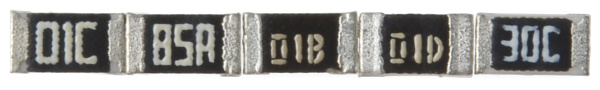
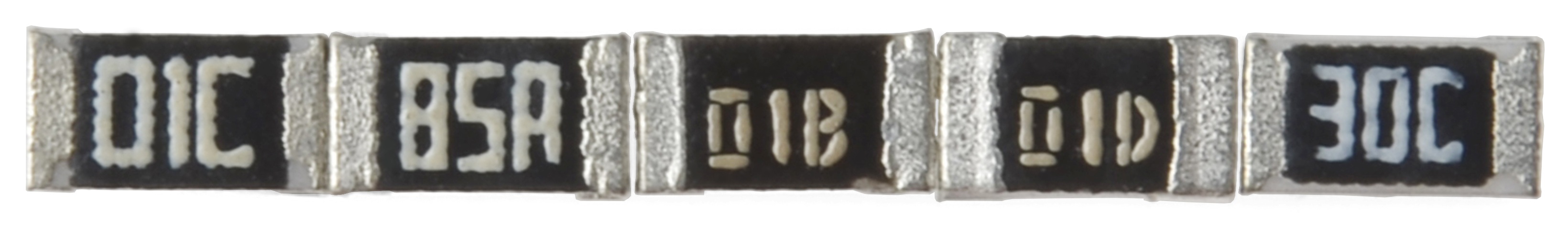
So a 01C resistor is our good friend, 10kΩ (100x100), 01B is 1kΩ (100x10), and 01D is 100kΩ. Those are easy, other codes may not be. 85A from the picture above is 750Ω (750x1) and 30C is actually 20kΩ.
Series resistors
When connected in series resistor values simply add up.
N resistors in series. The total resistance is the sum of all series resistors.
So, for example, if you just have to have a 12.33kΩ resistor, seek out some of the more common resistor values of 12kΩ and 330Ω, and butt them up together in series.
Parallel resistors
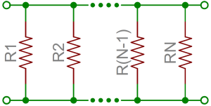
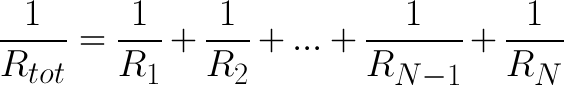
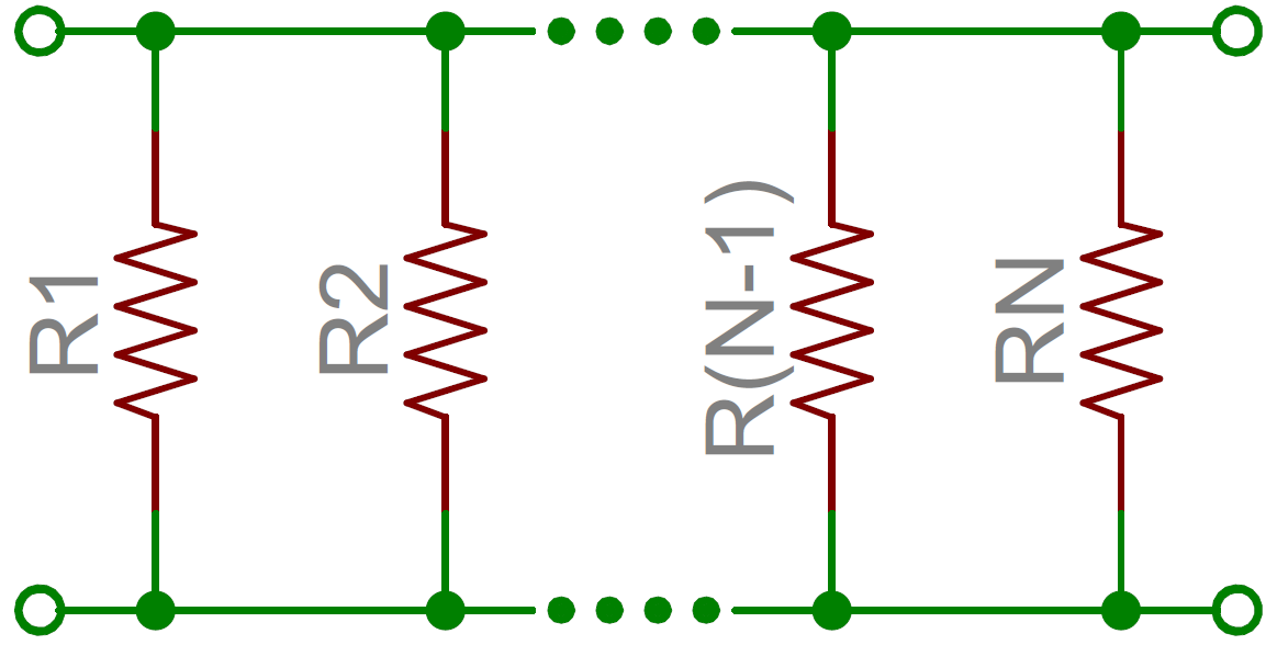
Finding the resistance of resistors in parallel isn’t quite so easy. The total resistance of N resistors in parallel is the inverse of the sum of all inverse resistances. This equation might make more sense than that last sentence:
N resistors in parallel. To find the total resistance, invert each resistance value, add them up, and then invert that.
(The inverse of resistance is actually called conductance, so put more succinctly: the conductance of parallel resistors is the sum of each of their conductances).
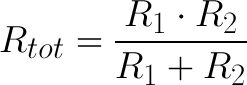
As a special case of this equation: if you have just two resistors in parallel, their total resistance can be calculated with this slightly-less-inverted equation:
As an even more special case of that equation, if you have two parallel resistors of equal value the total resistance is half of their value. For example, if two 10kΩ resistors are in parallel, their total resistance is 5kΩ.
A shorthand way of saying two resistors are in parallel is by using the parallel operator: ||. For example, if R1 is in parallel with R2, the conceptual equation could be written as R1||R2. Much cleaner, and hides all those nasty fractions!


Comments
Post a Comment